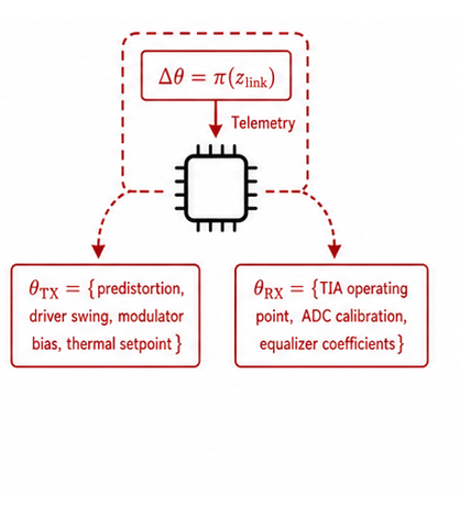
Slower, event-driven supervisory adaptation
Coordinating electrical, photonic, and DSP adaptation from link-level observables.
Several coupled electrical, photonic, and DSP mechanisms can produce the same decline in link margin. A fast local loop may correct the symptom, but without higher-level context it can select the wrong actuator, consume unnecessary power, or disturb another loop. This work explores hierarchical in-circuit intelligence that uses link-level observables to coordinate slower supervisory decisions with fast local adaptation—seeking corrections that remain effective, power-aware, and stable as optical links become more complex.
Slower, event-driven supervisory adaptation
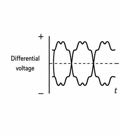 Electrical dataDifferential voltage
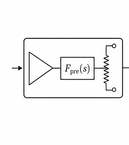 High-speed driver and predistorterFpre(s) and driver swing
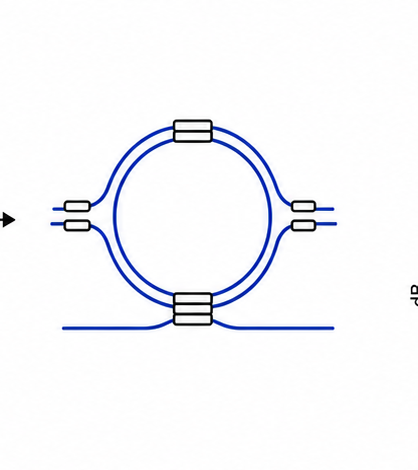 Optical modulatorMRR or MZM
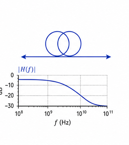 Optical channelChannel response |H(f)|
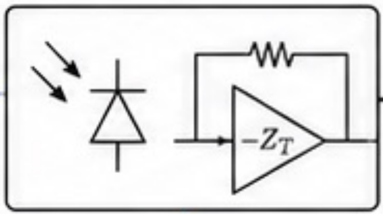 Photodetector and TIAPhotodiode and −ZT
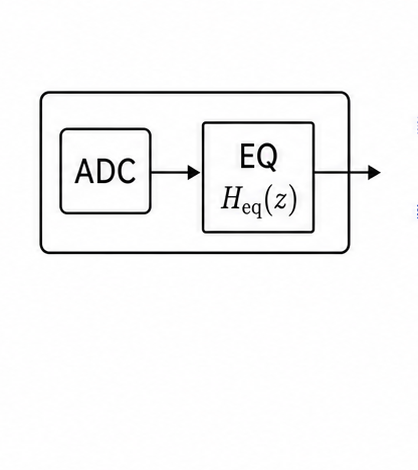 ADC and equalizerADC calibration and Heq(z)
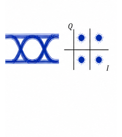 Recovered dataEye and I/Q observables
Predistortion · driver swing · modulator bias · thermal setpoint
TIA operating point · ADC calibration · equalizer coefficients
Relate link-level penalties to electrical, photonic, and channel mechanisms.
Distribute correction across coupled actuators under margin and power constraints.
Verify the hierarchy through co-simulation, hardware-in-the-loop control, and optical-link experiments.
Does coordinated correction restore useful operating margin?
How quickly does the hierarchy select and settle the correction?
What power cost accompanies the recovered performance?
How often does supervision alter a loop that did not need correction?